
If you have been working on x86 disassembly and moving on to ARM disassembly, one of the subtle differences you may notice is the lack of byte aligned opcodes in ARM (or THUMB) instruction set. Being based on RISC, ARM architecture provides fewer instructions as compared to x86. The need to implement an instruction set having functionally similar instructions as their x86 counterparts, only using fewer (and perhaps smaller) instructions gave rise to the instructions where opcodes are not dictated by bytes but by bits.
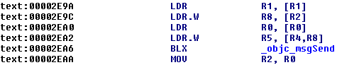
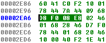
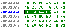
One of such intriguing instructions in ARM is BLX. BLX instruction performs a PC relative unconditional branch, and optionally changes mode to ARM or THUMB depending on the target address. It encodes to a 32-bit word under THUMB mode 2. It’s encoding varies depending upon the relative offset between the instruction and the target address. For e.g. the instruction at 0x2EA6 in the disassembly above encodes to D8 F0 08 E8 while another BLX instruction at 0x30C4 encodes to 8E F3 C4 E9. The encoded instruction itself is divided into two 16-bit halves, each of which is shown in little-endian. The actual encodings are therefore F0 D8 E8 08 and F3 8E E9 C4. The encoding is explained in the THUMB instruction set (available here).
Calculating the offset
The instruction at 0x2EA6 branches to _obj_msgSend, which is at 0xDAEB8. The offset for encoding is calculated from the current value of PC which is 4 bytes ahead due to pipeline, i.e. 0x2EAA. When the target of branch is 32-bit ARM code, the value used is align(PC, 4), which is PC rounded down to align it to 4 bytes, i.e. PC & 0xFFFFFFFC (0x2EA8 in this case). The offset is therefore, 0xDAEB8 - 0x2EA8 = 0xD8010.
Encoding the instruction
The offset is then used to encode the instruction as follows:
Offset = 0xD8010

      00            0D            80            10

Bits 31-24         23-16         15-8           7-0
   0000 0000     0000 1101     1000 0000     0001 0000

Bits 31-25      24 23 22       21-12          11-2         10
     0000000     0  0  0     0011011000     0000000100     00
                 S I1  I2         H              L

J1 = ~I1 ^ S = 1
J2 = ~I2 ^ S = 1

Encoded instruction:

Bits 32-28    27       26-17      16-15 14 13 12     11-1          0
               S          H             J1    J2        L
     11110     0     0011011000     11  1  0  1     0000000100     0

      1111 0000     1101 1000     1110 1000     0000 1000

         F0            D8             E8           08
which explains the encoding seen in the disassembler (D8 F0 08 E8). :-)